
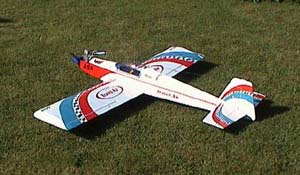
| Black Horse Travel Air |
 The
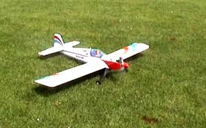
Black Horse Travel Air has been available in the UK for a few years
now. In this time the price has gradually fallen to the point where you
can now pick up this low wing sports model for £50. But, what do you
get for your money and is it £50 well spent. Having seen a club mate's
example flying well, I decided to find out.
The
Black Horse Travel Air has been available in the UK for a few years
now. In this time the price has gradually fallen to the point where you
can now pick up this low wing sports model for £50. But, what do you
get for your money and is it £50 well spent. Having seen a club mate's
example flying well, I decided to find out.
Open
The Box
The box the model comes in often gives you an idea of what to expect.
This one looked good, with big colour photos and relevant information.
Lifting the lid (still in Al's Hobbies before buying it) gave an idea
of the quality - it's impressive. The model itself is well presented,
each part being in it's own plastic bag for protection with another bag
containing accessories. The airframe itself looked well built with all
the parts fitting together well, no huge gaps and good use of glue. The
wood isn't balsa, I've no idea what it is, but I wasn't expecting it to
be on a £50 model.
 The
covering is of the sticky back plastic type (again, no surprises there)
but is very well fitted. I have to say it's a better job than my own covered
models. The colour scheme itself is in film. The accessories are better
than I was expecting and were used throughout. I'm sure some will choose
to replace them with branded items but that's your choice. The only issue
I did have was with the aluminium tubes running down the back of the fuselage
for the control rods. The rods have to enter and exit these tube square,
otherwise the friction will stall the servo(s).
The
covering is of the sticky back plastic type (again, no surprises there)
but is very well fitted. I have to say it's a better job than my own covered
models. The colour scheme itself is in film. The accessories are better
than I was expecting and were used throughout. I'm sure some will choose
to replace them with branded items but that's your choice. The only issue
I did have was with the aluminium tubes running down the back of the fuselage
for the control rods. The rods have to enter and exit these tube square,
otherwise the friction will stall the servo(s).
Once home the first thing to do was read the manual, which was not much help. It lacks the detail required to help less experienced modellers. While the photos are nice they don't show you what you want to see. The text is written in reasonable English but contains a lot of typos. The radio installation is covered with one photo while the photos of the aileron servo installation bear no resemblance to the parts in the box! The only really useful page is last one, which has control surface travel, C of G etc. etc.
Lets
Get Down To It
So, down to building... The first operation is to install the wing servos.
These are fitted onto the bearers glued to the back of the servo hatch,
with the arm sticking up through the hole in the hatch. You'll need a
longer than standard servo arm for it to clear the hatch. I used a HiTec
adjustable arm. A pull through string is already installed in each wing
panel to help you pull through the servo lead (with extension lead fitted
and plug/socket secured well), which really speeds up the job. Remember
to poke the lead up through the hole in the top wing skin once you've
revealed the hole from under the film. Tape the leads well out of the
way of the wing root. Now would also be a good time to set up the aileron
push rods. This is self-explanatory using the parts in the kit & photo
in the manual.
Wing
Joining
The next step is joining the wings. The first step here is to check how
well the wing joiner fits into the slot in each wing half. In my case
it was a very loose fit. So a strip of 1/16 balsa was slid in under the
joiner when gluing. By contrast a club mate (who bought his on the same
day at the same time from Al's!) found his to be too big and required
sanding to fit. Also, remember to sand off the glue used to hold the pull
through string in place, as it will stop the root ribs mating closely.
Oh, and cut the film away from over the bolt holes on the bottom wing
skins and put in a pair of bolts half way. When it finally comes to joining
the wings, make sure you use lots of Epoxy (30min+) on every single part
of the join including the rib faces. Once it's all in place, one strong
elastic band should be stretched between the wing dowels while another
should be placed across the wing bolts (that's why they're put in early).
Once dry a slip of film/sticky tape supplied covers the join. That's the
wings done!
Fuselage
The fuselage comes in a very complete state. All the pushrods are in place,
with the engine mount installed. In the past there have been a few issues
with Black Horse metal engine mounts fracturing during flight. 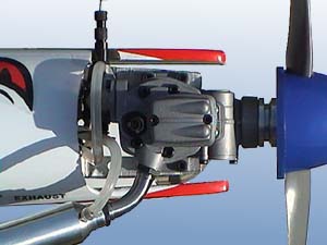 However
the mount on the front of our model looked far more substantial. It also
had the correct bolt hole positions for the T nuts in the firewall. So
it was used, after all the sharp radii of the beams had been filed to
a more rounded shape.
However
the mount on the front of our model looked far more substantial. It also
had the correct bolt hole positions for the T nuts in the firewall. So
it was used, after all the sharp radii of the beams had been filed to
a more rounded shape.
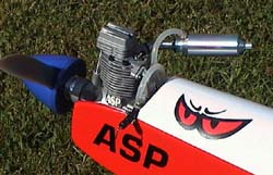
Another alteration had to be made as we used an ASP .61FS (more of that later). This was instead of using the standard system - a plate clamps the engine lug in place and is bolted to the mount fore and aft of the lug. We used the front hole in the mount and drilled a second so that the engine could be bolted with M3 bolts direct to the mount. This allowed us to move the engine far enough forward that the carburettor would clear the top fuz decking (see photo). All that was then left to do was to move the throttle snake round to meet the new carb location.
Next the tank and radio bays were sprayed with Flair Spectrum fuel proofer just in case the slightly cheap looking tank let go. The tank itself was installed next; note the piece of wood inside the fuz shaped to meet the lip on the front of the tank. The wood's there to stop the tank coming into contact with the engine mount bolts, so make sure the tank goes in the right way! Lastly open up the slots in the back of the fuselage and poke out the control rods, it's easier to cut these openings neatly now rather than when the tail is in place.
 Tail
End
Tail
End
The tail feathers are next on the agenda. The first job being perhaps
the most risky in ARTF construction - cutting the film from the tail plane
centre and fin base. The most important thing to remember here is 'Do
not score the wood underneath' as it will weaken the tail and fin. You
don't want those coming off in flight! The best method I've found here
is to start off with a very sharp blade. Hold it almost parallel to the
surface so that more of the blade is in contact with the film. This makes
it easier to feel how deep you're cutting. Once this is done the tail
and fin can be glued in place. I used 5 min epoxy here to leave more time
to get things lined up, although the manual specifies a particular brand
of Cyano. Once the glue's dried, the various bits of hardware can be attached
and connected up to the rods exposed earlier.
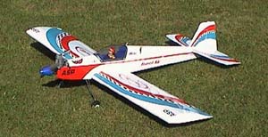
The supplied tail wheel can also be attached at this point. Last job on the exterior is to fit the undercarriage. My advice here is to ditch both the saddle clamps and also the whole wire U/C. The joints between the two wires break lose very easily leaving the wheels to go back up through the wing skin. Something all the Travel Air's I've seen, have done - not nice. A GRP unit would be better or re-do the stock item with fuse wire and solder. On the reviewed model the stock item was used, but only until a better unit could be sourced. (The flying photos have the Carbon Copy item fitted).
 Radio
Installation
Radio
Installation
The Travel Air makes this bit quite easy. The servo tray is pre-installed,
all you need to do is put everything in place. A word of caution however,
on the servos. The wood that the tray is made out of is not the greatest
for self-tappers; a 1.5mm pilot will help this. The hole in the front
of the servo tray will take a switch very nicely. I had to leave the on/off
plate off so that the bit of wire would fit through the toggle. This then
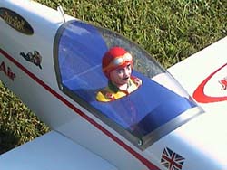
exited the side of the fuz to allow the switch to be turned on/off. The
battery and Rx went up in the space ahead of the servos, while the aerial
ran up and out behind the cockpit (through some fuel tube), to be secured
at the tail.
The control travels were all set up on a trusty Sky Sport 4 to the recommended travel. The actual test flight was carried out with my Eclipse 7 radio, but setting it up on the SS meant it had to be done properly! The C of G was checked and found to be in the right place while a few extra stickers (including a few supplied by JE with the engine) made the model look at least slightly different than standard.
 Engine
Set Up
Engine
Set Up
The first trip to the field was used only to bed in the engine (being
ringed) as I was in a Fun Fly comp. However from the running we did and
from more recent use, it's clear that this is one nice engine. As it is
our first four-stroke we were expecting a bit more trouble than usual,
but we followed the comprehensive instructions and the engine behaved
itself all the way. The first start was instant via a poke with the starter;
while the needle settings were spot on. The engine showing a very fast
transition from the word go. By the end of the first run it would hold
a very low idle as well as a good top end. The engine has continued to
improve since gradually providing more power as it beds in. Not bad for
£100 eh?
 Getting
The Model Into The Air
Getting
The Model Into The Air
The flying, perhaps the most important bit which I'm sure many will have
scrolled down to read first... The second time the Travel Air was taken
out (the following Sunday) started with a few engine runs. Once happy
that it was holding full power even with the model pointed nose up (an
old control line method to make sure the engine isn't lean) it was time
to go! The model was taxied out to the end of the patch making full use
of the tail wheel, before being lined up into wind.
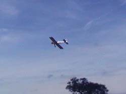
Slowly increasing the throttle to full saw the model begin to roll. The tail came up very quickly and within ten metres she was up and away. Once up to a safe height the stall was tested. Well, I say tested, there really isn't one! It just sits there nodding a bit, losing a bit of altitude as it goes - nice. The standard rates are just about right, although the elevator is a bit more powerful than the ailerons.
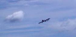
 Basic
aerobatics were tested consecutive loops and rolls are easy to do and
the rolls are reasonably axial. The rudder works quite well so knife-edge
flight could just about be sustained with the standard set up. Inverted
wasn't a problem either - just the prerequisite bit of down elevator.
Basic
aerobatics were tested consecutive loops and rolls are easy to do and
the rolls are reasonably axial. The rudder works quite well so knife-edge
flight could just about be sustained with the standard set up. Inverted
wasn't a problem either - just the prerequisite bit of down elevator.
All in all it flies very well, with no nasty surprises waiting to get you. Landing is very simple; if you can land a trainer you can land this. There's nothing nicer on a summer evening than flying this model round the sky to the burble of that four stoke... Would I recommend it? Yep!
The
Black Horse Travel Air is available from:
All major Hobby Stores
including Al's Hobbies
Web
Site:
www.alshobbies.com
| Technical Details - Black Horse Travel Air | |
| UK Distributor | Irvine Ltd |
| Aircraft Type: | Sport |
| RRP | £50 approx. (£44.25 Al's Hobbies web site) |
| Wingspan | 62" |
| Wing Area | 650sq ins |
| Engine | .40 -.46 two stroke. (ASP 61FS used) (Just Engines) |
| Weight | 6lbs |
| Radio Used | HiTec 8ch, HS-301's |
| Number of Channels: | 4 Channels (5 servos) |
| Control Functions: | Ailerons,Elevator, Rudder, Throttle |
| Construction | ARTF (wood) |
| Likes | Dislikes |
|
|
Please
mention 'Flying Sites' when contacting
Al's Hobbies
| Info Panel |
|
Black
Horse
Travel Air |
| Comments: All in all it flies very well, with no nasty surprises waiting to get you. |
| Price: £50 approx |
| See Technical Details Below |