
| Freescale Partenavia |
 Not
wanting to let the electric revolution to pass me by, I decided it was time
to dive into this developing side of our hobby. But what should I buy? With
my interest in scale models I wanted an aircraft that not only looked good
but one that was also a little unusual.
Not
wanting to let the electric revolution to pass me by, I decided it was time
to dive into this developing side of our hobby. But what should I buy? With
my interest in scale models I wanted an aircraft that not only looked good
but one that was also a little unusual.
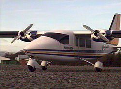
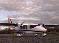
I started to think of a twin-engined aircraft. Not something I would normally contemplate with I/C engines. Something out of the ordinary was what I needed, but what? With so many Twin Stars about I had to look hard! Then I saw it! Slough Radio Control Models (not now available from Slough RC Models) have regularly advertised in the magazines and there it was leaping out of the page at me! The Partenavia! A semi scale, all foam ARTF kit that looked fantastic. And at £69.99 a good price too. It had to be the one.
New
To The Game
Being new to the electric game I had to consider the extra expense of
batteries, charger, speed controller etc. Still it was going to be a one
off expense and I would have all the right gear for the future. So off
to the Sandown Show in June with my shopping list. On the Slough Models
stand the Partenavia was selling like hot cakes. I had to move quickly.
The electric motors are not included in the price but Slough Models had
a purpose made package containing two 480 motors, suppressers and two
Gunther props for an extra £14. Another quick dash around the stands
found me with a Super Nova charger and two 1900 mAh power packs. When
I found a Jeti 35 amp speed controller my shopping list was complete.
After a great day out at the show it was time to get home and build my
new acquisition. (Plesae note that the Partenavia can be bought direct
form the German manufacturers at www.freescale.de
or from UK distributor Sola Models)
 Building
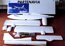
The Partenavia was not only my first electric model but also my first
ARFT kit. So upon opening the large glossy box I was greeted with a well
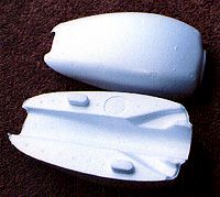
packaged but surprisingly small number of parts. Foam parts include the
complete fuselage, fin and top decking, wings in two sections, horizontal
stabiliser and canopy. Also included were a comprehensive hardware pack,
wheels, spats and an aluminium undercarriage, GRP control horns, piano
wire snakes, clevis's, even an elastic band to hold the canopy on. What
at first glance looked like a rolled plan was in fact a very large sheet
of stickers that, as we shall see, are an integral part of the building
process. A well produce instructional booklet is also included. A useful
tip before you start building is to give all the foam parts a gentle sanding
with a light grade paper or wet & dry (used dry). This process removes
most of the small moulding pimples that are present on most of the pieces.
 So
where to start?
So
where to start?
Well, looking at the instructions would be a good place! But not being
one for convention I decided that I wanted to get 'stuck' into that sticker
sheet. My thinking behind this move was that it would be easier to handle
the foam parts before some of them were joined together.
I would advise that you take a long hard look at the sticker sheet and work out exactly where to cut. Each printed piece has been squeezed onto the sheet and because you use not only the coloured parts but also the clear sections it takes some time to work it all out. The old adage 'Think twice cut once' is very good advice in this case.
The largest stickers are those that cover the top of the wings. From trailing edge to wrapping around the leading edge you have to be very careful that creases do not appear. It is almost impossible to correct any errors at this stage. The clear part of the stickers acts as a top hinge on all control surfaces.
Once all the stickers were on the aircraft, it seemed almost ready to fly. This is the first model that I have ever constructed, that was 'decorated' before it was built!
Back
on Course
So now I moved back to the instruction sheet and followed their building
methods. This begins by gluing all the nylon threaded grommets (M4) into
their appropriate holes in the fuselage. These grommets eventually take
the four wing bolts (M4 x 40mm) and the steel bolts (M4 x 12mm) to mount
the aluminium undercarriage. All gluing is with 5-10 minute epoxy except
for the gluing of the wing's wooden main spar, where I used 24 hour epoxy.
The grommets are pushed home by first attaching the bolts to them. But
do apply some light oil or Vaseline to the bolts to prevent them sticking
to the grommets!
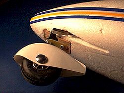 After
fitting the liteply receiver shelf behind the cockpit it time to assemble
the steerable nose wheel and main undercarriage. This is very straightforward
and the instructional diagrams are very precise. The pre bent nose leg
is mounted in a hard wood block that in turn is glued into a recess in
the nose. I found that the hole in the hardwood block needed easing out
a little to give a free but positive rotation of the nose leg. All three
wheels are provided, as are some very light weight ABS spats. All these
assemble in a conventional manner.
After
fitting the liteply receiver shelf behind the cockpit it time to assemble
the steerable nose wheel and main undercarriage. This is very straightforward
and the instructional diagrams are very precise. The pre bent nose leg
is mounted in a hard wood block that in turn is glued into a recess in
the nose. I found that the hole in the hardwood block needed easing out
a little to give a free but positive rotation of the nose leg. All three
wheels are provided, as are some very light weight ABS spats. All these
assemble in a conventional manner.
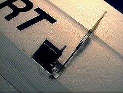
Next, select the correct push rod and sleeves (snake) for elevator and rudder/nose wheel activation. In the kit I had these where .8mm piano wire with a white 2mm outside diameter sleeve. Don't confuse the orange 3mm tube, as this will be used as an rx aerial guide.
The push rods and sleeves are next epoxied into their appropriate slots on the inside surfaces of the fuselage. GRP horns are fitted to the control surfaces and the provided connectors are then put in place. The rear top decking and fin are fitted after the horizontal stabiliser. All parts fit together well and most have male and female location lugs moulded into them.
 Wing
& Motors Installation
Wing
& Motors Installation
The wing halves are joined ensuring that they are straight and level and
the motors are then glued in place. I decided to pre-wire my motors. The
motor pack came with a set of suppression diodes and a pair of Gunther
props. Having taken advice on the 480 motors I decided to use 4mm silicone
wires to supply the current. This however, caused a few problems later
on! The wings have separate servos in them. These require the fitting
of servo extension leads. Now, with all these leads lying about in the
wing, where do they all go? Well, a long narrow slot has been moulded
in the underside of the wing to carry them all. A 1 metre long 5mm x 10mm
spruce spar is glued into this slot with all the wiring buried underneath.
My dilemma was to get all my cabling to fit under the spar without the
spar sitting proud of the underside of the wing!
I managed to ease out the slot with some careful sanding and specially made sanding blocks, so that in the end it all the wiring disappeared under the spar… just!
 The
wings and fuselage have holes moulded into them to take mini servos. I
used Super Tec Naros. You could also use Hitec HS-81's if you wish. Any
larger servos and you'd have to open up the moulded holes to take them.
I don't think however, that the small extra weight of large servos would
unduly hamper the aircraft's performance.
The
wings and fuselage have holes moulded into them to take mini servos. I
used Super Tec Naros. You could also use Hitec HS-81's if you wish. Any
larger servos and you'd have to open up the moulded holes to take them.
I don't think however, that the small extra weight of large servos would
unduly hamper the aircraft's performance.
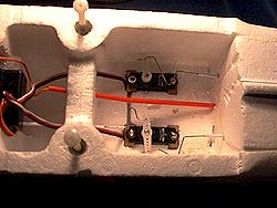
Servo
Installation
Instructions suggest that you glue your servos directly into the foam.
I've never fancied permanently gluing any radio gear, so I used servo
tape for the wing servos and made up small balsa bearers for the elevator
and rudder servos. Once all servos and linkages are complete, you can
then cut though the foam to release the control surfaces. Doing it this
way allows everything to be aligned correctly. This prevents any major
adjustments at either the control horn or servos.
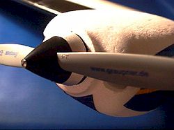 One
final deviation, but one that I found worthwhile, was to buy a pair of
Graupner spinner/adapters. They are a little expensive at £8.95
each, but with 6x4 Graupner props, they do really finish of the motor
installation very nicely. In fact the model in the box photograph utilises
these spinners. So, decide for yourself, but I don't think you'll be disappointed.
One
final deviation, but one that I found worthwhile, was to buy a pair of
Graupner spinner/adapters. They are a little expensive at £8.95
each, but with 6x4 Graupner props, they do really finish of the motor
installation very nicely. In fact the model in the box photograph utilises
these spinners. So, decide for yourself, but I don't think you'll be disappointed.
This just about finishes the building side of the Partenavia. Mount the battery (1900Mah 8 cell pack in my case) and a speed controller. I used the Jeti 35 controller. Then check the balance point. The correct CG should balance the model on the main spar, at 77mm from the leading edge. My aircraft needed a small piece of lead placed in a slot right at the tail end of the fuselage, to balance the model without too much of a nose down attitude.
 Flying
The Partenavia
Flying
The Partenavia
As with any new model, my club mates gathered around to have a look. All
had complimentary comments to make about the Partenavia's good looks!
One of the great revelations to me, as a 'new to electrics' flyer was
the lack of fuss and bother getting the model prepped at the flying site.
No oily fuel and rags, no glow batteries and starters. Just bolt the wing
on, stuff a power pack in the nose and away you go! I didn't even have
to think whether I had charged my receiver battery!
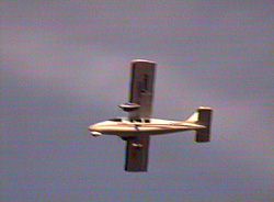
So, with my cameraman Paul (Pylon) Board at the ready, I pointed her nose into wind and opened up the motors. The Partenavia accelerated quickly away and after a conservative distance I gently pulled back on the stick. Bowling down our tarmac runway the wheels made quite a racket! As she lifted off, everything went quite eerily silent. But she continued to climb. Several clicks of down trim were introduced. This settled her into a much more subdued gentle climb.
Time to throttle back a little. I immediately felt right at home with this model. Turns were very smooth with little or no tendency to drop her nose. And in spite of the flat bottom wing section, there was no tendency for the model to zoom upward after fast banking turns.
 The
Partenavia covered the sky remarkable quickly on this very still day.
A few low passes for the camera, then after about seven or eight minutes
I could feel that the power pack was coming to an end. After a long banking
turn onto finals I levelled her out and she floated on quite some distance,
but touched down perfectly.
The
Partenavia covered the sky remarkable quickly on this very still day.
A few low passes for the camera, then after about seven or eight minutes
I could feel that the power pack was coming to an end. After a long banking
turn onto finals I levelled her out and she floated on quite some distance,
but touched down perfectly.
On
Reflection
I have since had another six or seven flight with the Partenavia. All
have been very enjoyable. Flight packs last on average about seven minutes.
The model is completely viceless and a joy to fly. I've found no tip stalling
tendencies; in fact you'd be hard pushed to get her to stall at all! Simple
aerobatics, loops and rolls are all possible if not very scale like. The
flimsiest parts of the model are those spats. They are very thin and easily
damaged on any surface other than the smoothest tarmac runway.
So, to sum up in a few words. If you like your (semi) scale models and you want to get into electric with something a little different then I thoroughly recommend you go out a get a Partenavia You won't regret it and it makes such a pleasant change to all those Twin Stars!
| Technical Details - Freescale Partenavia. | |
| Manufacturer | Freescale (Available Direct) |
| UK Distributor | Sola Models Uckfield, East Sussex |
| Aircraft Type: | ARTF Twin Electric Foam Semi Scale |
| RRP | £84.99 |
| Wingspan | 1500mm (59") |
| Wing Area | 21.4 dm² (480 sq ins) |
| Wing Section | Clark Y Mod. |
| Weight | 1400g (49ozs) Test Model 56ozs |
| Length | 1080mm (42½") |
| Number of Channels: | 4 Channel Radio / 4 Servos |
| Control Functions: | Aileron, Elevator, Rudder, Throttle (ESC) |
| Motors: | 2 x Speed 400 or Speed 480 |
| Battery Pack: | 8 Cells - 1250 to 2400 mAh |
| Likes | Dislikes |
|
|
Please
mention 'Flying Sites' when contacting
Sola Models
| Info Panel |
| Comments: A great introduction to electric flying! |
| Price: €124.95 |
| See Technical Details Below |
| Click
Here For Mpeg Video Clip (2.9Mb) |