
| Aviation Designs Exocet |
|
Just visible is the vertical whip aerial that I found increased ground range by about 15% and will in future always use for an extra margin of safety. The Rx aerial is simply shortened by the length of the whip so the final overall total is the same as the original. |
|
A 12-volt battery in the conventional flight box powers the igniter box. Also needed is a tank of propane (12kg) to fill the fuel tank (1.6 litre) in the model. This is out of the shot away from the start up area for obvious reasons. There is some stuff to cart about but not as bad as if you go pylon racing. |
 This
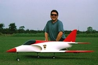
is me with the finished model to give some idea of its size. The reason
for the smile is that the first few test flights had been successful
and everything had gone exactly as planned. Even after all these years
of flying it's still a relief when it works out all OK especially
when it's your own model you are test flying! This
is me with the finished model to give some idea of its size. The reason
for the smile is that the first few test flights had been successful
and everything had gone exactly as planned. Even after all these years
of flying it's still a relief when it works out all OK especially
when it's your own model you are test flying! |
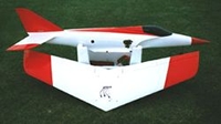
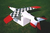 Underneath
of the model showing the chequerboard scheme. At 200 mph plus its
good to have an idea of which way up the model is! The metal tail
pipe can just be seen at the rear of the model poking out slightly,
seems not to have a detrimental effect on thrust. Underneath
of the model showing the chequerboard scheme. At 200 mph plus its
good to have an idea of which way up the model is! The metal tail
pipe can just be seen at the rear of the model poking out slightly,
seems not to have a detrimental effect on thrust. |
 Shot
showing the crow braking effect. Flaps down and ailerons up. This
system slows the model down to a walking pace with the turbine still
running and the ailerons going up effectively adds washout to the
wings and helps stabilise things coming into land - less chance of
a wing tip dropping as things slow up. Shot
showing the crow braking effect. Flaps down and ailerons up. This
system slows the model down to a walking pace with the turbine still
running and the ailerons going up effectively adds washout to the
wings and helps stabilise things coming into land - less chance of
a wing tip dropping as things slow up. |
|
Two separate air tanks are used; one for the retracts and one for the brakes to ensure an adequate supply of air to stop the model after landing. The turbine is mounted in the blue bracket with the black intake shroud over the compressor intake clearly visible. The nylon propane feed is connected via the Festo fitting and the yellow tygon tubing is the line for the oil tank pressure, the oil feed and its regulator are on the top of the turbine and not visible in this shot. The blue/yellow Sullivan snake that can be seen is the linkage to the throttle valve on the side of the turbine. Snake inner has solid 2/56 wire running end to end. |
|
The blue valve on the plywood mount is for the attachment of the pressure gauge; max. power being obtained at 1.1 bar. The Festo fitting is the break point used for filling the onboard propane tank. The green wire collector tubes house the servo leads; just behind the oil tank are the twin elevator servos and the rudder servo. The yellow servo arm is the one operating the retract valve; the receiver and battery pack are forward of this location. Just visible at the rear of the canopy frame is the clear tube housing the receiver aerial to the whip. The switch/charging socket are also in there but out of shot. It all goes in but needs to be well planned prior to cutting and gluing. |
|
You can just see a clevis attached to the needle - this is the throttle linkage. The black circle at the bottom left corner is the cover for the oil tank fill valve. Fly (if you can spot it) was illegal passenger, probably ejected soon after start up. |
|
The pushrods to each of the elevator halves can be seen well clear and in no danger of getting too hot. |
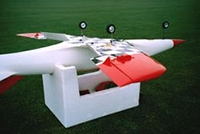
 Model
taken apart ready to go back home after another successful outing.
Custom made carrier is from an old polystyrene box and ensures model
doesn't rattle about in transit. Model
taken apart ready to go back home after another successful outing.
Custom made carrier is from an old polystyrene box and ensures model
doesn't rattle about in transit. |
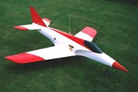 The
finished model ready to go - it took best part of a year to get
it to this stage. It is sprayed with Flair Spectrum paint. Red nose
cone at front houses 200g of lead shot needed to get the C/G in
the right position despite the fact that I had inched the turbine
forward anticipating it would come out tail heavy. Nevertheless
it was only 100g over the top weight quoted in the instructions
(7kg).
The
finished model ready to go - it took best part of a year to get
it to this stage. It is sprayed with Flair Spectrum paint. Red nose
cone at front houses 200g of lead shot needed to get the C/G in
the right position despite the fact that I had inched the turbine
forward anticipating it would come out tail heavy. Nevertheless
it was only 100g over the top weight quoted in the instructions
(7kg). 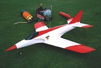 View
from the other side, much the same as photo.1. In the background
is the required starting gear. The aqualung is used to get the turbine
spinning together with an igniter box to give a spark, the gas valve
is then opened and we have ignition.
View
from the other side, much the same as photo.1. In the background
is the required starting gear. The aqualung is used to get the turbine
spinning together with an igniter box to give a spark, the gas valve
is then opened and we have ignition. 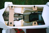 What
things look like inside the fuselage with the wing removed. The
stainless steel propane fuel tank is visible underneath the extension
leads that connect to the wing servos - the ferrite cores are on
the aileron leads as these are longer due to the fact that the servos
are located outboard in the wing. The quick disconnect is for the
retracts; the one for the brakes is there too lurking beneath the
plywood brace.
What
things look like inside the fuselage with the wing removed. The
stainless steel propane fuel tank is visible underneath the extension
leads that connect to the wing servos - the ferrite cores are on
the aileron leads as these are longer due to the fact that the servos
are located outboard in the wing. The quick disconnect is for the
retracts; the one for the brakes is there too lurking beneath the
plywood brace. 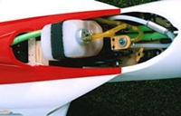 View
under the canopy showing the oil tank and oil lines to the turbine.
Note carbon band around oil tank acting as a burst protector and
metal tank cap. All lines are attached with clips - an oil loss
spells disaster and will ruin the ceramic bearings within seconds.
This needs to be avoided at all costs hence the precautions above.
View
under the canopy showing the oil tank and oil lines to the turbine.
Note carbon band around oil tank acting as a burst protector and
metal tank cap. All lines are attached with clips - an oil loss
spells disaster and will ruin the ceramic bearings within seconds.
This needs to be avoided at all costs hence the precautions above.
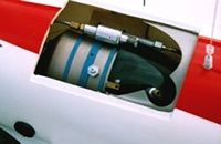 This
is a shot of the view with the top fuselage hatch removed ready
for starting. The igniter plug (white) is visible along with the
hook up for the air supply (brass fitting). The gas regulator valve
is seen at the top; the knurled adjuster is for setting the max.
pressure.
This
is a shot of the view with the top fuselage hatch removed ready
for starting. The igniter plug (white) is visible along with the
hook up for the air supply (brass fitting). The gas regulator valve
is seen at the top; the knurled adjuster is for setting the max.
pressure. 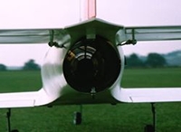 Rear
end shot with nothing glowing just after a run up the way is should
be. The metal fixing at the bottom of the fuselage outlet anchors
the metal tail pipe together with a screw at the top into the wooden
block.
Rear
end shot with nothing glowing just after a run up the way is should
be. The metal fixing at the bottom of the fuselage outlet anchors
the metal tail pipe together with a screw at the top into the wooden
block. This model was designed around the JPX turbine and as such there is room to get all the associated paraphernalia in the model with a bit of forethought.
The current crop of kero-burners would easily fit. It differs from the Kangaroo/Hotspot derivatives as the turbine is fully enclosed; as such this brings its own challenges but it would make a good second model once you know how to set-up/start the turbine.
This is not meant to be a kit review in the classical sense, as you will need to have some building and flying experience to contemplate this type of model in the first place and hence will be more than able to handle putting it all together.
There is a fair amount of work involved (makes a change from all the ARTFing), the components/instructions are very good quality - follow these and the model goes together a treat with no nasty surprises. The kit includes: -
-
White gelcoat epoxy-glass fuselage
- Epoxy-glass
inlets
- Access
hatch
- Obechi
pre-sheeted wings, tail and fin
- All
ply/wood pre-cut
- ABS
accessories (cockpit/servo covers)
- Clear
canopy
- Full size plan and instructions
To complete the model the following were used: -
Turbine (JPX 250P, this one produces 5kg thrust). A flying mate and myself have been using the propane JPXs (all versions, 240/250 and 260) for over 5 years and not once have we experienced any starting or running problems.
The engines have never flamed out on us; they keep running until they are shut down or run out of gas. They are up and running quicker than most folks take to start a glow motor. They are absolute jewels built to a quality and reputation that set the standard in the turbine world.
Scour the Internet and you might pick one up at a bargain price (perhaps in the region of £750, remember they were the best part of £3000 new).
Radio
gear (Futaba 9 ZAP) with high quality servos (model has a total of 11)
are essential in this type of model. These are all powered from a single
2400 mAh Nicad with on board monitoring and were set-up as follows: -
-
Aileron 1 (Futaba 3002, metal geared mini).
-
Elevator - a servo (Futaba 9202) was used on each elevator half; one
needs to be reversed for this application. This allows solid wire pushrods
to run alongside the tailpipe for an easy set up. I felt this was safer
than installing the servos in the tail and running the servo leads along
the hot tail pipe.
- Throttle
(Futaba 9101) operated via a servo slow to take into account the lag
in spool up and spool down times. Too rapid throttle opening can result
in large increases in temperature stressing the turbine bearings.
-
Rudder (Futaba 3001, Kevlar closed loop running on top of the tail pipe)
and another (3001) on the noseleg (3001) with a Y lead.
- Flap
1 (JR 3321, metal geared mini).
- Flap
2 (JR 3321) - JR servos were used as I had them in stock.
-
Aileron 2 (3002). This 4-servo wing arrangement allows for the provision
of crow braking on landing. For this the flaps are lowered about 45
degrees and the both ailerons raise 6mm.
Mixing in 2mm down elevator compensates for the trim change. This is available in the glider menu of the ZAP with the airbrake function becoming the throttle. I haven't checked with the model but I'm sure it doesn't know the difference between it and a glider! This slows the model down incredibly on landing; the effect is remarkable to see.
-
The crow is mixed to one of the sliders on the side of the Tx so it
can be brought in proportionally as landing conditions (strength of
wind etc.) dictate. You need a tight set-up for this (linkages must
be spot on and slop free) so that there is no undue wing-rocking coming
into land when crow is deployed.
Takes a while to set-up but is very worthwhile and permits the model to be landed with the turbine running hence allowing a go around if necessary (always good to have this margin of safety).
- Emergency
cut off for the turbine fuel supply (Futaba S136G retract servo). This
can be operated at the flick of a switch and the failsafe also functions
on this valve. It is set up in a non-return mode so that if the failsafe
cuts in the supply remains off even when the servo goes back to its
initial setting - operated via a slotted quadrant on the valve.
- Retracts
(Ripmax SD250 micro servo).
Having run out of channels the wheel brakes are operated by a micro switch on the application of full down elevator; hard to believe that the ZAP is working to its full extent.
Undercarriage
Spring air heavy duty, slim line retracts.BVM
wheels and brakes. Some might consider these a bit expensive but you need
to be able to stop a jet instantly and the BVM units do the job. Once
you have used these no others will ever get a look in.
Metal
Tail Pipe
The turbine is totally enclosed so you need to protect the fuselage from
the 700 degrees C exhaust. A titanium tail pipe with a bell mouth was
fitted that had been wrapped in ceramic foam blanket held in place with
heat resistant aluminium tape; this is anchored to the fuselage with mounting
blocks and screws and centred on the turbine tail cone with steel standoffs
in the bell mouth. This works fine, it is possible to hold the rear of
the fuselage with the turbine running and only just feel things starting
to get warm.
Weight
The final all up weight was 7.1 kg (15.6 lbs) and with 5 kg of thrust
this gives a top speed of over 200 mph. This is plenty fast enough and
for most of the time more than adequate aerobatic performance is attained
at half throttle, this also means that the flight time can be extended.
Performance
I am very pleased with the models performance; it rockets into the
air on full power even from a grass strip and is rock solid on the ground,
will even handle a cross wind well. In fact it is like a turbine powered
F3A (aerobatic) model, very smooth flight characteristics and can land
in a small area due to the crow braking.
The accompanying photographs show the model in a bit more detail and explain some of the aspects of what in the end has turned out to be quite a sophisticated model.