

| Building The Boeing B52 For The Slope (Part 1) |
Clwyd Soaring Association
(Click Here for Part Two)
 The
story began in December 1986, when Chris Walker, a friend of mine, unearthed
a stack of Aeroplane Monthly magazines, which had been printed in mid
1981. The magazines contained a series of articles, written by Bill Gunston,
on the history of the B52 Stratofortress. On reading these articles I
recognised the inner spark of enthusiasm, which always initiates the development
of any large project.
The
story began in December 1986, when Chris Walker, a friend of mine, unearthed
a stack of Aeroplane Monthly magazines, which had been printed in mid
1981. The magazines contained a series of articles, written by Bill Gunston,
on the history of the B52 Stratofortress. On reading these articles I
recognised the inner spark of enthusiasm, which always initiates the development
of any large project.
Brief
History of the B52
The
Boeing B52 Stratofortress, arguably the world's greatest bomber, was conceived
in Seattle during the mid forties under the intense pressure of the cold
war, to fulfil an urgent need.
The variant chosen for this model, the B52D, took part in the Vietnam 'Linebacker 11' operation, which has since been called the B52's finest hour.
The power plant consists of eight-10,000 lbs st. Pratt & Whitney J57-P19W turbo jet engines. The fuel capacity is in excess of 40,000 US gallons and it carries a crew of six. Its armament includes four ½" machine guns in a tail turret, eighty-four 500lb bombs in its bomb bay, and twenty-four 750lb bombs on under wing pylons.
The last B52 to he constructed rolled off the line in 1962, and it is remarkable to note that the basic design was so sound that the Stratofortress has been able to continue its service life into its fifth decade. In fact United States Air Force experts expected at least three hundred to remain in its active service inventory for the remainder of the 20th Century. And they still are in service!
Design
of the Model
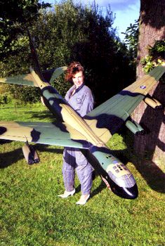
After studying scale drawings of the B52, I soon became aware that the
proportions of this awesome aircraft could be extremely good for a Power
Scale Soaring (PSS) model. I realised that it would be possible to retain
the exact scale dimensions of the aircraft, although it would be necessary
to increase the scale size of the flying control surfaces. The sweepback
on the massive wings of the B52 is 37º and this angle has been faithfully
reproduced on the model. The scale chosen was 1/16th, which gave a wingtip
to wingtip (swept) span of seventeen feet! The fuselage length came out
at eleven and half feet. An early decision was made to use polystyrene
foam and obechi veneer as the basic construction materials. A 'prototype'
chuck glider was then built to test the centre of gravity, stability and
general flying characteristics. The results of the testing removed all
doubt regarding the feasibility of the project.
Fuselage
Construction
The fuselage is a 2" square balsa/plywood composite box. A pair of
spruce longerons runs the length of the fuselage, on top and bottom, to
provide extra strength. The fuselage shell was made in three sections,
which faithfully follow the contours of the full size machine.
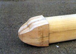 The
nose section was built by laminating five pieces of balsa, which were
then carved to the correct shape. This is not the easiest way to produce
the nose, but I felt that this method of providing the necessary extra
weight in the nose would be better than adding ballast weights later on.
The amount of carving was enormous but I really enjoyed making one great
pile of shavings!
The
nose section was built by laminating five pieces of balsa, which were
then carved to the correct shape. This is not the easiest way to produce
the nose, but I felt that this method of providing the necessary extra
weight in the nose would be better than adding ballast weights later on.
The amount of carving was enormous but I really enjoyed making one great
pile of shavings!
Each fuselage section consisted of a top and bottom panel, with the three lower panels being joined to form a keel. A 2" square section internal box was constructed from balsa/plywood composite to form a spine. The top panels were then glued into position.
It was decided at this stage, to make the fin tail plane removable to facilitate transport and storage. The enormous size of the model led to a decision to position a servo as close as possible to each control surface so three separate servos were used, one for each elevator half and one for the rudder.
 The
tail plane halves incorporated a Graupner 10 mm wing joiner with an 8
swg piano wire rib, and a spring was stretched across the fuselage to
retain them in position. Provision was made for the tail plane incidence
to he adjusted, just in case!
The
tail plane halves incorporated a Graupner 10 mm wing joiner with an 8
swg piano wire rib, and a spring was stretched across the fuselage to
retain them in position. Provision was made for the tail plane incidence
to he adjusted, just in case!
The removable fin was achieved by constructing the lower portion in the form of a spigot, which slotted into a locating female box built into the rear section of the fuselage. To retain the fin and rudder assembly in position, a horizontal pilot hole was drilled right through the fuselage to provide access for a brass bearing tube to be inserted; a piano wire pin feeds through to hold the unit in position during flight.
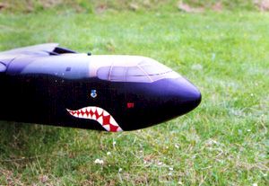
The tail gun on the model was made from balsa, plastic and brass tubes, which gave a very realistic appearance.
The scale length of the bomb doors was reduced to negate any possibility of weakening the fuselage structure. The bomb doors which were made from balsa/plywood laminate with internal stiffening ribs, are operated by a retract servo with pushrods and ball joints incorporating some fancy geometry!
The wing position was marked onto the fuselage and this section was then sawn out. The blank, which was removed, was used later as the wing fairing. A 1/8th plywood base was glued to the horizontal surface of this cut out and 1/8th plywood bulkheads were attached fore and after, interlocking with the box, to provide wing bolt and dowel mountings.
Wings
The wing panels are awe inspiring, with a root chord of two feet and
a tip chord of 7". The leading edge of each wing panel is over nine
feet long. Two full-length spruce spars (¼" x ½")
were inserted into the foam on the top and bottom surfaces of each wing.
These were covered in obechi veneer. The flap and aileron were marked
on each panel and then cut out. The wings, ailerons and flaps were then
fitted with leading and trailing edges. Servo cut cuts were placed in
position to operate each flap and aileron with as short a push rod as
possible. Servo extension wires were run through the wings to these boxes,
using drinking straws as conduits. Block balsa wing tips were then fitted
and shaped, after which the main wing joints were installed.
 The
wing joining arrangement proved to be the most difficult construction
problem with this model. The main wing joiner was a 15mm Graupner steel
strip that incorporated a brass outer. The front joiner (or incidence
bar) was made from 10mm Graupner strips and set into plywood boxes which
were inserted between the front and rear wing spars to give maximum torsional
strength. Once the system had been set up 3/8th plywood root ribs were
added and shaped.
The
wing joining arrangement proved to be the most difficult construction
problem with this model. The main wing joiner was a 15mm Graupner steel
strip that incorporated a brass outer. The front joiner (or incidence
bar) was made from 10mm Graupner strips and set into plywood boxes which
were inserted between the front and rear wing spars to give maximum torsional
strength. Once the system had been set up 3/8th plywood root ribs were
added and shaped.
The wings were held to the fuselage by two rear wing bolts, one in each half, with dowels locating each half in the forward bulkhead. The system has since proved to be more than adequate.
With the wings in situ, the piece that had previously been cut from the fuselage was shaped to form the wing fairing, veneered on the inside for strength and had a 1/16th ply face added to its front and rear edges.
The scale position of the engines was then marked onto the wing panels and a template was constructed to produce the engine pylons. It was necessary for the engine/pylon assembly to he given a 'knock off' capability.
The pylons were constructed from ¼" balsa with 1/16th plywood facings each side. A Gelutong plug was carved to represent the engine nacelle and 0.040 styrene was vacuum formed over the plug to make top and bottom nacelle sections. These were joined by installing a ¼" plywood former between the two halves. The 'knock off' capability was provided by means of a front locating pin with a spring clip at the rear, this would be necessary when affecting a landing on rough terrain.
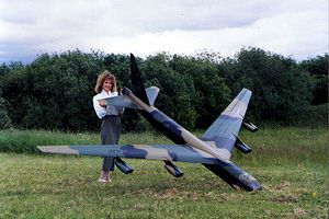
The B52 airframe was assembled to check everything was ship shape and Bristol fashion. My first thoughts on seeing this glorious site (to me anyway) was how long would it be before the little men in white coats would arrive to take me to the funny farm!
Next month, finishing, radio instalation, final touches and the maiden flight!
(Click Here for Part Two)
Ray Jones
Clwyd Soaring Association